# AffBotics
# Esp32 Brain
Code running on the main controller.
# Working Environment
Tools:
* Enveronment: ``PlatformIO``
* Framework: ``Arduino``
* Code editor: ``Visual Studio Code``
* MQTT Broker: ``shiftr.io``
Hardware:
* Mcu: ``ESP 32``
# How to build and Flash
Setup Visual studio Code
--------------------------
The VS code setup Instructions are available in Getting Started.
* Setup Visual studio code according to the Host operating system.
* Install PlatformIo extension inside VS code
* Make sure that ESP32 Dev Module is selected, and Framework as Arduino
Building and Flashing Application:
----------------------
To build the application, clone the `affbotics_software` repo and go to the folder `ESP32_AGV_brain`
* Pull the repository locally
* Navigate to the directory ``affbotics_software/firmware/avg/ESP32_AGV_brain/``
* Select the COM port
* Click Upload
# Program Flow
Basic Workflow:
----------------
Firmware is present in ``affbotics_software/firmware/avg/ESP32_AGV_brain/src/main.cpp``
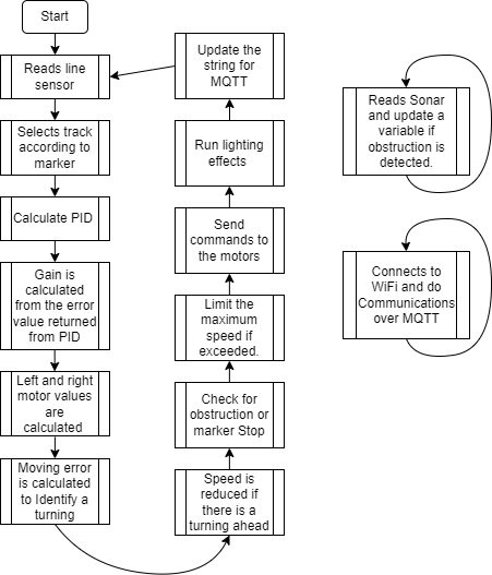
* Esp32 will connect to the wifi when booted
* It will read the line sensor and Ultrasonic sensor calculate the values and sends commands to the motor via Modbus
Am a Geek:
------------
* WiFi ssid and password can be changed by editing ``const char ssid[]`` and ``const char pass[]``
* MQTT broker can be changed by editing the line ``client.connect("esp32", "public", "public" ))`` and ``client.begin("public.cloud.shiftr.io", net);``
* PID values can be tweaked by changing values of variabled ``kp, ki, kd``
# Line Sensor
# Working Environment
Tools:
* Enveronment: ``PlatformIO``
* Framework: ``Arduino``
* Code editor: ``Visual Studio Code``
Hardware:
* Mcu: ``STM32G030C8T6``
* Magnetic Sensor: ``QMC5883``
# How to build and Flash
Setup Visual studio Code
--------------------------
The VS code setup Instructions are available in Getting Started.
* Setup Visual studio code according to the Host operating system.
* Install PlatformIo extension inside VS code
* Install STM32 Platform in PlatformIo
* Install Board support packages for STM32G0C038T6
* Select the board and Framework as Arduino
Building and Flashing Application:
----------------------
To build the application, clone the `affbotics_software` repo and go to the folder `Line_sensor`
* Pull the repository locally
* Navigate to the directory ``affbotics_software/firmware/avg/Line_sensor/``
* Select the COM port
* Click Upload
# Program Flow
Basic Workflow:
----------------
Firmware is present in ``affbotics_software/firmware/avg/Line_sensor/src/main.cpp``
* Line sensor communicates using Modbus over RS485
* The Modbus I registers from address ``0X1000`` to ``0X1003`` can be read to obtain number of tracks, markers, Left track error and Right track error
Am a Geek:
------------
* Modbus Register address and ``SLAVE_ID`` can be changed by changing ``#define`` values
* Uncomment the line `` #define DEBUGMODE 1`` to continuously print raw sensor readings in CSV format through serial.
* Track and marker threshold values can be tweaked by changing ``#define trackThreshold`` and ``#define markerThreshold``
# Experiments
### Nov-25-2022
#### NFC tests
- We have tested the possibility of having some instructions flashed into the NFC tags so that the AGV can read and process the data on the fly, but it turns out that its only possible while the AGV is moving slowly otherwise it can't read the data reliably. [image](https://cdn.discordapp.com/attachments/884335599962693633/1045657879593635850/image.png)
# BLDC driver
# Working Environment
Tools:
* Enveronment: ``PlatformIO``
* Framework: ``Arduino``
* Code editor: ``Visual Studio Code``
* FOC: ``Arduino Simple FOC``
Hardware:
* Mcu: ``STM32G030C8T6``
# How to build and Flash
Setup Visual studio Code
--------------------------
The VS code setup Instructions are available in Getting Started.
* Setup Visual studio code according to the Host operating system.
* Install PlatformIo extension inside VS code
* Install STM32 Platform in PlatformIo
* Install Board support packages for STM32G0C038T6
* Select the board and Framework as Arduino
Building and Flashing Application:
----------------------
To build the application, clone the `affbotics_software` repo and go to the folder `BLDC_driver`
* Pull the repository locally
* Navigate to the directory ``affbotics_software/firmware/avg/BLDC_driver/``
* Select the COM port
* Click Upload
# Program Flow
Basic Workflow:
----------------
Firmware is present in ``affbotics_software/firmware/avg/BLDC_driver/src/main.cpp``
* BLDC driver board communicates using Modbus over RS485
* The Modbus I registers ``0x2000`` can be Writen with a value from -200 to 200 for setting the velocity of the motor.
* Where -ve values spin the motor in the opposite direction
* comment the line ``#define IAM_LEFT`` for Right motor or leave it uncommented for Left motor
Am a Geek:
------------
* Modbus Register address and ``SLAVE_ID`` can be changed by changing ``#define`` values
* Motor PID values can be tweaked if needed using `` motor.PID_velocity.P, motor.PID_velocity.I, motor.PID_velocity.D``
* change the phase angle ``motor.P_angle.P`` and direction ``motor.initFOC(0, Direction::CW);`` if required.
# BaseAGV
# Setup Base AGV
### Assembly
Once the robot is taken out of Packaging , place it on a flat surface floor.Depending on your robot type you will have to install the battery type.
For robot supporting SLA battries , please install 3 12V 7 AH battries using the connectos provided and . Once the battries are connected please Switch on the Robot. with the on button behind the robot ( MCB Connector ).
### Setup
For the first time the robot needs instructions on how to move around and how the RFiD tags are to be interpretted.
Please lay down the track to connect the locations which need to be connected together. Avoid sharp turns and have enough space around the track so that robot can pass.
Place the first RFiD tag on the locationion the robot needs to take any actions
### Programming
Press the start button on the robot for it to move towards the Tag , make sure the robot line sensor is on the track.The robot will start moving waiting for a new tag.
The Robot will stop once it reaches a unknown Tag , Using the touchpanel select instruction for the tag. Then press the Start button again and the robot will contine to move to next tag.
If your track is not a round track then please place RFid Tags on the end of the tracks to tell the robot to turn around.
### Charging Setup
To setup Charging place the charging port somewhere along the track preferably next to a stop, This is not activated till the robot does not come over it ( It waits for a rfid to activate ) .
### Call to a station
All RFiDS can be used as a station and a robot can be called to one using Either the phone app or the the Wifi calling hardware provided.